Description:
Explore the control signals used in an 8-bit breadboard computer in this 13-minute video. Dive into the construction of control logic, examining memory and RAM input signals, instruction register input signal, subtract signal, and output signal. Learn about the program counter, resets, and the use of LEDs to indicate active control signals. Discover additional components like hex inverters and red gel for enhancing signal interpretation. Gain insights into building and understanding the intricate workings of a basic CPU, with practical demonstrations and explanations suitable for electronics enthusiasts and computer architecture students.
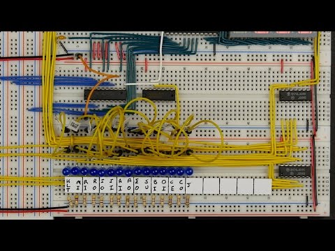
8-Bit CPU Control Signal Overview
Add to list
#Computer Science
#Computer Architecture
#Engineering
#Electronics
#Electrical Engineering
#Circuit Design